IT organizations need to support a variety of applications running on a bewildering range of infrastructures. On the one hand, traditional applications like financial and ERP systems are often running on bare metal servers. On the other hand, virtual machine environments, with their own infrastructure requirements, host an increasing share of applications and services like virtual desktops. On top of that, recent years have seen the hybrid and private cloud applications that require yet another type of on-premise infrastructure.
Beyond the sheer complexity of managing multiple physical infrastructures, it is inefficient, as well. Having hardware dedicated to specific types of infrastructure requires overbuilding in order to manage capacity. For example, the servers running your ERP system may have idle capacity, but it cannot be used to run private cloud workloads. As a result, excess capacity needs to be built into the private cloud infrastructure to absorb workload spikes and maintain room for development activities and new applications.
Composable infrastructure has emerged as a datacenter architecture to solve these complexity and inefficiency problems facing IT organizations. In this post, we explain composable infrastructure and how HPE Synergy has implemented it to provide a compelling next-generation datacenter computing platform.
What Is Composable Infrastructure?
Ideally, IT organizations would like to manage a single physical infrastructure that could be dynamically configured to support all types of workloads. So, for example, the excess capacity on an ERP server could be reconfigured to the virtual machines, containers, and web servers needed for a mobile app project that is under development.
This vision, of an adaptable and flexible physical environment that can be configured to support a variety of logical infrastructure, is known as composable infrastructure. A composable infrastructure provides pools of resources - compute, storage, and networking fabric - that can be automatically configured to support various application needs. An application’s requirements for physical infrastructure are specified using policies and service profiles. The composable infrastructure provides intelligent management software, with deep knowledge of the hardware, to interpret the specifications and compose a logical infrastructure meeting the application’s requirements.
In order to engineer a platform to realize this composable infrastructure vision there are several design principles to observe:
- Software Defined Infrastructure
- Fluid Resource Pools
- Hardware and Software Architected As One
- Physical, Virtual, and Containerized Workloads
Software Defined Infrastructure
A composable infrastructure needs to be built on top of a software defined infrastructure (SDI). In an SDI, physical resources can be defined and configured with machine readable code (e.g., configuration files, templates). Moreover, orchestration software can read these configurations and make calls to an application programming interface (API) to configure the underlying hardware as defined. For example, the specification might indicate that a server needs a 10GbE connection to a particular database. The orchestration software would then make the necessary API calls to the appropriate networking switch to allocate the 10GbE ports. To a large extent, IT administrators do not need to get involved with the configuration process. Intelligent software determines how to compose resources from the pools of compute, storage, and network fabric.
Fluid Resource Pools
As mentioned, a composable infrastructure needs to provide fluid pools of compute, storage, and networking resources. All resources in the pools need to be immediately available for configuration and deployment to support a workload. For example, if a web application experiences a spike in traffic, additional web servers and bandwidth must be allocated from the pools, configured, and deployed to handle the additional workload. Likewise, unused resources must be reclaimed and put back in the pools. So, when the traffic spike has passed, and the additional web servers and bandwidth are no longer needed, the underlying physical resources are returned to the pools. This may involve deleting VMs to free up disk space and releasing networking ports. The exact implementation details are handled by intelligent management and orchestration software.
Hardware and Software Architected As One
At this point, you may be wondering how this magic can possibly happen. The SDI needs a unified API to programmatically manage all the compute, storage, and networking resource in the pools. In addition, the management and orchestration software needs a detailed understanding of the physical properties of all the hardware. And, of course, the hardware needs to support programmable configuration and be flexible enough to handle a wide range of scenarios. For example, gear in the networking pool must support the dynamic configuration of ports, bandwidth, and security policies.
To make this happen, the software and hardware need to be architected together. To some extent, the software defines the requirements for the hardware. The unified API must be supported in the hardware. But, beyond that, the hardware must meet the definition of composability specified in the software. For example, if the software layer provides templates for a virtual desktop infrastructure (VDI), then there need to be server, storage, and networking resources in the pools that can support VDI. At a minimum, that means servers where hypervisors can be installed, data storage that can be attached with low latency and high bandwidth to the virtual machines, and a network that can be configured to deliver the bandwidth required to support the expected number of simultaneous end users.
Physical, Virtual, and Containerized Workloads
As mentioned in the introduction, IT organizations today are managing separate infrastructures for traditional, virtualized, and cloud-based applications. Those disparate workloads are not going away anytime soon, so if IT is going to standardize on a composable infrastructure, then it must support the composability of bare metal, virtual machines, and containers (e.g., Docker). Otherwise, the vision of a composable infrastructure will not have been realized.
What is HPE Synergy?
HPE Synergy is the platform designed and marketed by Hewlett Packard Enterprise (HPE) to deliver composable infrastructure capabilities to the datacenter. Released in 2016, HPE Synergy is regarded by many as the leading platform for composable infrastructure. HPE has been investing significant engineering effort, over many years, to develop Synergy. The engineering effort continues today as the Synergy platform continues to expand and improve. Their efforts are paying off as Synergy is catching on with customers. In 2018, Synergy was HPE’s fastest growing new technology category, reaching over 1,600 customers and generating over $1 billion in annual revenue. In the sections below, we describe the various components of the HPE Synergy platform and how they are designed to work together to provide a truly composable infrastructure.
HPE Synergy 12000 Frame
The HPE Synergy 12000 Frame is a 10U rack-mountable unit that aggregates compute, storage, networking fabric and management modules in a single enclosure. The frame provides the foundation of an HPE Synergy Composable Infrastructure. Uniquely architected to work with the intelligent software management capabilities provided by HPE OneView, multiple HPE Synergy Frames can be linked together to scale the infrastructure while maintaining a single view of the entire network.
A single frame can support a wide variety of different modules and configurations vary depending on the workloads and software applications. You can find a variety of reference architectures in HPE’s Information Library including configurations to support popular applications such as: SAP HANA, VMware Cloud Foundation, Oracle Database as a Service, VDI, Citrix XenApp, SAS 9.4, and many more.
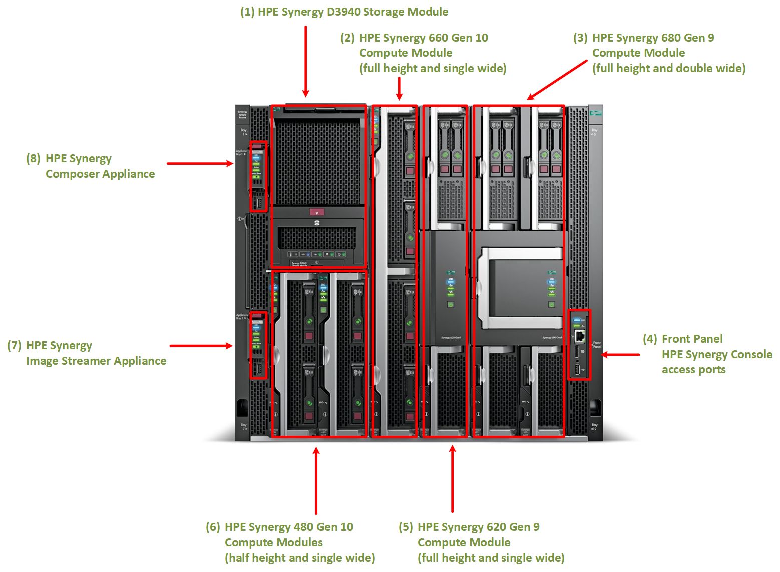
Figure 1 below shows the front view of an HPE Synergy 12000 Frame configured to illustrate the variety of different modules that are available. Up to 12 2-socket blade servers, or a combination of data storage modules and servers, can be installed in a single frame. The various modules, numbered (1) - (8), are discussed in more detail in later sections.

Figure 1. HPE Synergy 12000 Frame - Front View
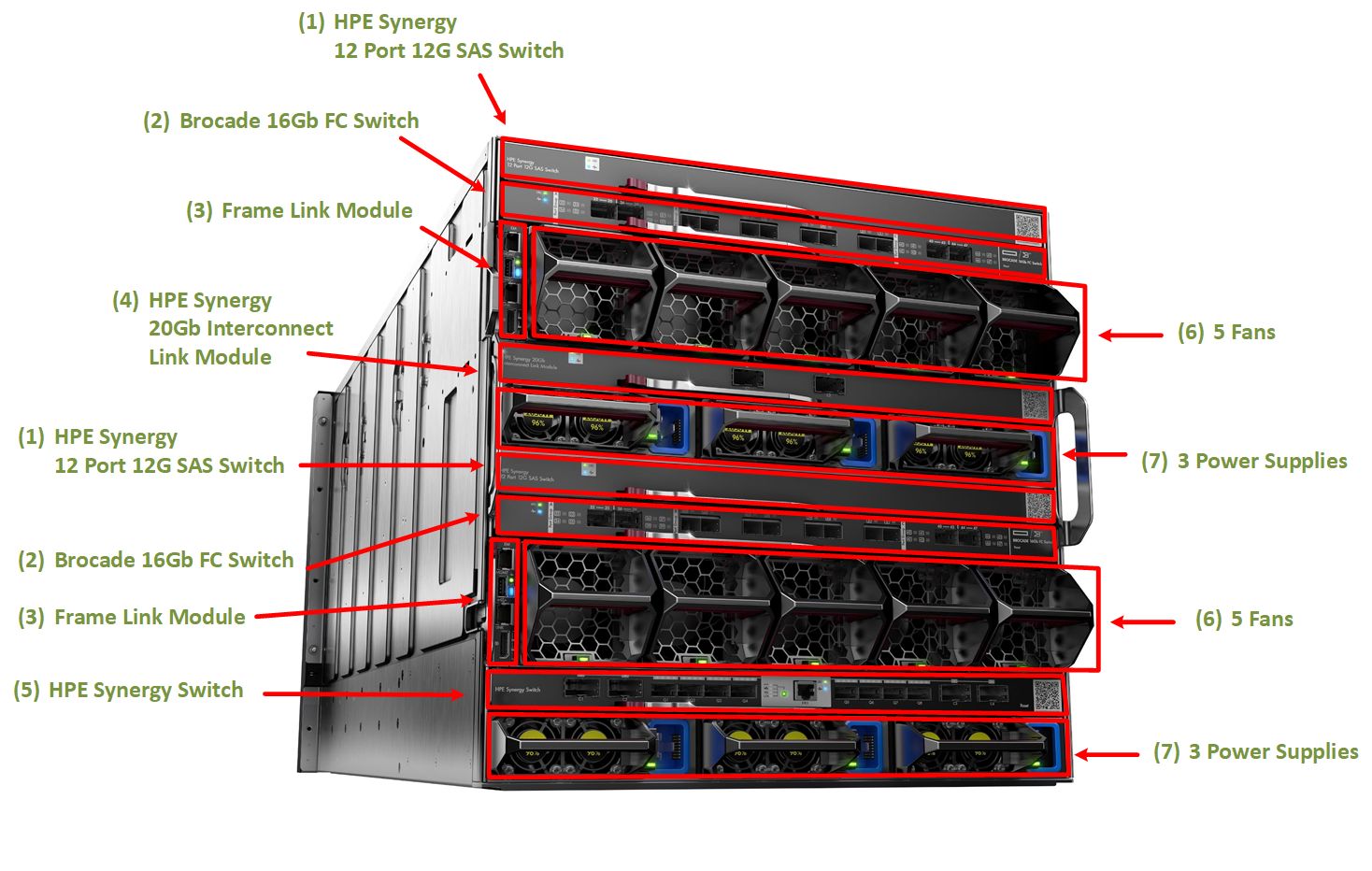
The rear view of the HPE Synergy 12000 Frame is shown below in Figure 2. Here, you can see examples of the various types of fabric modules that are available. A frame has 6 interconnect bays that can be configured for up to 3 fabrics (e.g., SAS, Ethernet, and Fibre Channel). Each fabric typically is supported by a pair of redundant interconnect modules.

Figure 2. HPE Synergy 12000 Frame - Rear View
In addition to the fabric modules, the rear view shows 10 fans and 6 power supplies. All 10 fans are required and at least 2 power supplies. The number of power supplies required depends on the requirements of the installed modules which can be determined by consulting the HPE Power Advisor Online.
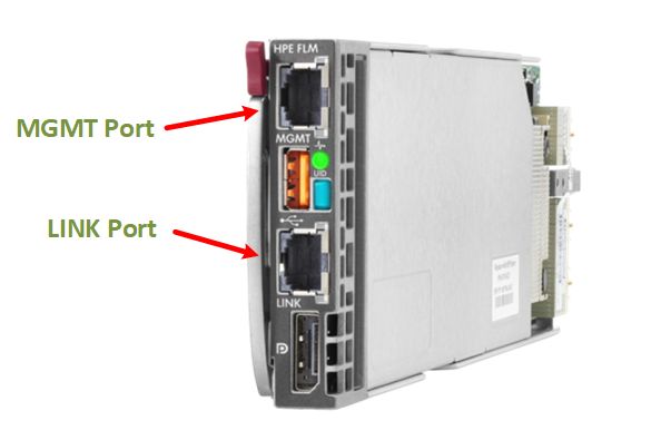
On the left side of Figure 2, notice that there are two frame link modules. These provide management uplinks and support the multi-frame ring architecture. Figure 3 shows a closeup view of a frame link module.

Figure 3. HPE Synergy Frame Link Module
Each frame link module contains a MGMT port for connecting to the management network and a LINK port for connecting multiple frames in a ring topology. For redundancy, each frame contains two of these modules.
Multi-Frame Architecture
A single frame can be managed individually simply by connecting the MGMT port of both of the redundant frame link modules to the management network. In this case, the LINK port is not used. Multiple frames can be managed as a system in this way, with each with an individual frame connected to the same subnet. However, this configuration is discouraged because it does not take advantage of important HPE Synergy management features such as uplink consolidation and automatic discovery.
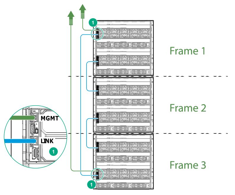
Figure 4, below, illustrates the preferred multi-frame architecture - called a ring topology, This diagram shows 3 frames within a single rack linked in a ring.

Figure 4. Ring Configuration of Frames
The frames are connected in a ring using the LINK ports on the frame link modules. As illustrated by the blue lines in Figure 4, Frame 1 connects to Frame 2 which connects to Frame 3 which connects back to Frame 1. Connectivity to the management network (green lines) is provided by a single uplink using the MGMT port on Frame 1 with a redundant uplink provided by Frame 3. Connectivity with the management network and between the frames is managed automatically by the frame link module and does not require user configuration.
The actual features that manage the Composable Infrastructure are delivered by the HPE Synergy Composer (see item 8 in Figure 1) which is described in the next post in this series.
About IIS (International Integrated Solutions)
This series of posts on Composable Infrastructure and HPE Synergy is published by International Integrated Solutions (IIS), is a managed service provider and system integrator with deep expertise in HPE Synergy. IIS is a distinguished HPE partner, winning HPE Global Partner of the Year in 2016 and Arrow’s North American Reseller Partner of the Year in 2017.
As a service provider, IIS brings broad datacenter experience as well as expertise in HPE Synergy. Having solved a myriad of problems for hundreds of customers, we bring a holistic view of the datacenter. In particular, IIS can help with:
- Sizing - providing an assessment methodology and tools to spec out your workloads.
- Migration Plans - helping you refresh your hardware and migrate applications to a HPE Synergy.
- Integration - understanding how to integrate your existing infrastructure with HPE Synergy effectively.
- Managed Services - providing remote monitoring and ongoing support for your composable infrastructure.


